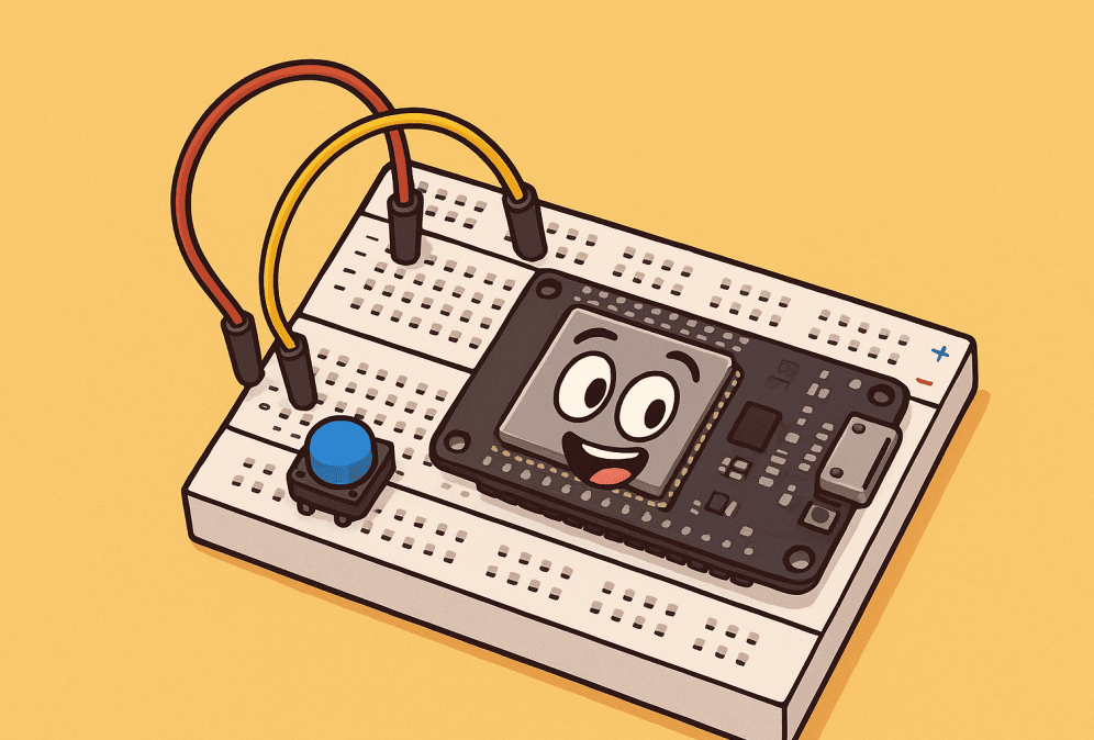
For every electronics developer, learning how to breadboard ESP32-WROOM-32D efficiently is often the first step from a vague idea to a stable, working prototype.
For a lively walkthrough, try our audio version below; the blog complements it with complete information for reference:
Among the many microcontroller modules available, one offers the ability to combine high-performance computing, wireless communication, and low power consumption: the ESP32-WROOM-32D. The breadboard, a seemingly simple plastic board, provides a flexible and low-cost testing platform for this module, allowing you to quickly test your ideas without the hassle of custom circuit boards.
However, effectively integrating these two components is challenging, involving a host of technical details such as pinout matching, power management, and programming connections. How can you overcome these obstacles and make them your go-to tools for development? The following content will reveal the answers.
Why use the ESP32-WROOM-32D breadboard?
The core value of the ESP32 development environment built on a breadboard lies in providing an efficient and flexible platform for validating ideas and testing code. For example, if you want to quickly implement a simple environmental monitoring device, there’s no need to wait for custom circuitry. Simply follow the tutorial to connect the ESP32’s GPIO pins to the temperature and humidity sensor and LED with jumper wires. After writing the code using Arduino, you’ll immediately see the results.
If you discover abnormal sensor data, you can simply replace the sensor and reconnect it. If the LED flashing rhythm isn’t right, simply modify the code parameters and reupload. This process eliminates the need for resoldering or redesigning the circuit, significantly reducing adjustment time compared to fixed soldered circuits. This significantly shortens the cycle from idea to verification, allowing every idea to be quickly tested.
This flexibility is what makes breadboarding ESP32-WROOM-32D the ideal starting point for IoT prototyping and testing.
What Can You Do with an ESP32 on a Breadboard?
1. Efficient Code Verification Platform: This provides a convenient environment for testing various code types. Whether it’s sample code from a tutorial or a custom program, you can quickly deploy it on the breadboard, observe its running status and output results in real time, and significantly shorten debugging cycles.
2. Multi-Device Collaboration: Leveraging the ESP32’s rich GPIO resources, you can simultaneously connect to a variety of peripherals, such as temperature and humidity sensors, light sensors, and small motors, enabling simultaneous collection, analysis, and coordinated control of multi-dimensional data, making it easy to build complex interactive scenarios.
3. Wireless Data Transmission and Remote Management: The module’s built-in Wi-Fi functionality simplifies data transmission, allowing you to quickly upload collected sensor data or device status information to cloud platforms (such as Alibaba Cloud and Blynk) or synchronize it to a mobile app, enabling remote real-time monitoring and intelligent management.
4. In-depth Exploration and Learning of Hardware and Software: Paired with the Arduino development environment, you can program targeted control logic for peripherals such as sensors, motors, and displays, gaining a deep understanding of the interaction between hardware and software. For beginners, this construction method is an excellent way to understand the workings of the ESP32. By connecting every pin and testing every function by hand, you can lay a solid theoretical and practical foundation before creating your own circuits.
5. Improve project success rate: Using a breadboard to build an ESP32 development board not only helps developers quickly acquire relevant knowledge and skills, but also allows them to verify their solutions and troubleshoot problems before officially building the final project, effectively reducing errors during actual production and significantly improving project success rates.
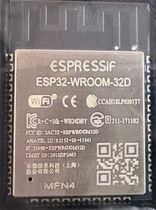
What is the ESP32-WROOM-32D?
It is a high-performance microcontroller module based on the D0WD chip, integrating Bluetooth and Wi-Fi dual-mode wireless communication capabilities. It is very popular in embedded development and the Internet of Things.
Core features include:
- A low-power design with a sleep current of only 5uA makes it particularly suitable for battery-powered devices.
- A dual-core processor (adjustable from 80–240 MHz) that easily handles complex computing tasks;
- 4MB–16MB SPI flash memory, providing ample storage and cache space;
- Support for Wi-Fi 802.11b/g/n and Bluetooth v4.2;
- A rich set of peripheral interfaces (PWM, ADC, DAC, GPIO, etc.) to meet diverse hardware connectivity needs;
- A low-power design with a sleep current of only 5uA makes it particularly suitable for battery-powered devices.
Why is breadboarding the ESP32-WROOM-32D difficult?
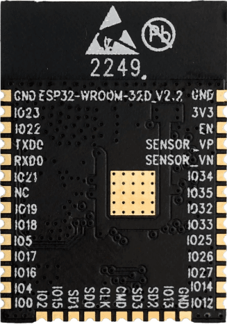
1. Pin Spacing Incompatibility: The module’s pin spacing doesn’t match the 2.54mm pitch of a standard breadboard, making it impossible to directly insert it into a breadboard. An adapter board is required for a stable connection.
2. Stringent Power Supply Requirements: The ESP32-WROOM-32D must be powered by a stable 3.3V voltage. Misconnecting it to a 5V power supply can easily damage the module, requiring even higher precision in the power supply circuit.
3. Lack of a Programming Interface: The module lacks a built-in USB port and cannot be directly connected to a computer for programming. An external USB-to-serial converter, such as a CP2102 or FTDI, is required, increasing the complexity of the connection process.
4. Soldering Required: The module’s pins cannot be directly adapted to a breadboard and must first be soldered to a breakout board or adapter. This presents a significant challenge for users without soldering experience, and improper operation can damage the module.
How to Breadboard ESP32-WROOM-32D Step-by-Step?
In this section, you’ll learn how to breadboard ESP32-WROOM-32D safely, connect all required components, and upload your first program. Now that we’ve identified the main challenges—pin spacing, power stability, and programming interface—let’s go through the complete step-by-step process to breadboard the ESP32-WROOM-32D safely and efficiently.
How to Build an ESP32-WROOM-32D Breadboard Circuit
Step 1: Gather all necessary components. Before wiring, you’ll need: the ESP32-WROOM-32D bare module, an ESP32 breakout board with 2mm to 2.54mm pitch, a standard 830-pin breadboard, male breadboard headers, a USB-to-serial adapter such as a CP2102 or FTDI (for programming), an AMS1117 LDO 3.3V voltage regulator (to safely power the ESP32), jumper wires for connections, a start/reset button, and 10uF and 0.1uF capacitors (to ensure stable power).
Tip: Choosing a breakout board with the AMS1117 and USB-to-serial connector pre-soldered can significantly save assembly time.
Step 2: Solder the ESP32-WROOM-32D to the breakout board. Because the module cannot be directly breadboarded, it must first be soldered to a breakout PCB with matching pins. To do this, align the module and breakout PCB. Using a thin-tip soldering iron (set to 350-370°C), carefully solder all edge pins, ensuring a secure solder joint. Then, connect the 2.54mm male header pins to the breakout board. Once completed, the module is ready for breadboard testing.
Step 3: Connect the soldered module to the breadboard. Position the module so that the pins on each side are inserted into different areas of the breadboard, leaving ample space between them for subsequent wiring and to avoid cross-wiring.
Step 4: Connect the power supply (make sure to use a 3.3V power supply). The ESP32 does not support 5V power supply, so you need to use an AMS1117-3.3 voltage regulator to create a power supply circuit: Connect a USB 5V adapter to the regulator’s VIN pin, connect the regulator’s output pin to the ESP32’s 3.3V VCC pin, and share the regulator’s GND pin with the ESP32’s GND pin. It is recommended to connect a 10uF capacitor between VCC and GND to improve power supply stability.
Step 5: Connect the CP2102/FTDI to the development environment (Arduino IDE or PlatformIO). The pin mapping is as follows: adapter TX to ESP32 RX (U0R), adapter RX to ESP32 TX (U0T), and both to GND. The adapter’s 3.3V pin is optional (connect only when powered by the adapter).Additionally, connect a start button to ESP32 GPIO0 and GND to manually enter flash mode.
Step 6: Program the ESP32. First, install the ESP32 board manager in the Arduino IDE and configure the board settings: select “ESP32 Dev Module” as the development board, select the corresponding COMx port, set the programming mode to “DIO,” and set the programming frequency to 40MHz. Once the settings are complete, upload test code (for example, blinking the LED connected to the GPIO2 pin).
Comparison between Breadboards and Development Boards
1. Size and Integration: The ESP32-WROOM-32D circuit built on a breadboard is more compact and suitable for space-constrained environments. The DevKit development board is slightly larger, but integrates more peripheral circuits (such as a USB port and voltage regulator), providing more comprehensive functionality.
2. USB Connection Convenience: Breadboard circuits require an external USB-to-serial adapter such as a CP2102 or FTDI to communicate with a computer, which involves more steps. The DevKit development board has a built-in USB port for direct plug-and-play connection to a computer, simplifying programming and debugging.
3. Power Supply Design: Breadboard circuits require a separate 3.3V voltage regulator such as the AMS1117 to create a power supply system, requiring manual power wiring. The DevKit development board comes with an onboard voltage regulator and supports direct 5V USB power, eliminating the need for a separate power supply circuit.
4. Entry Points: Breadboard construction requires soldering the module to the breakout board, which demands a certain level of soldering skill. The DevKit development board, on the other hand, is a pre-installed device that requires no soldering at all. It’s plug-and-play, making it easy even for beginners to get started quickly.
5. Cost vs. Time Tradeoff: The breadboard solution offers lower material costs and is ideal for developers working with limited budgets. However, it takes more time to assemble since each connection and power line must be wired manually. The DevKit development board is slightly more expensive but saves significant time on soldering, wiring, and other setup steps—perfect for efficiency-focused developers.
6. Breadboard Compatibility: After soldering the breakout board properly, the ESP32-WROOM-32D can be securely mounted on a breadboard for stable testing. Meanwhile, the DevKit development board already comes with pin spacing that matches standard breadboards, allowing direct insertion without any additional processing.
Regarding applications, what can you build with this setup?
-
- Build a low-power WiFi sensor, leveraging its low power consumption for long-term data collection and transmission;
- Develop a wearable device with Bluetooth Low Energy (BLE) functionality, communicating with mobile phones and other devices via Bluetooth;
- Build a node based on the MQTT/HTTP protocol, connecting it to an IoT platform for device interoperability;
- Build a Wi-Fi-based smart home controller for remote control of home devices.
After extensive breadboard testing, the ESP32-WROOM-32D not only supports most of the DevKit’s functions, but also offers cost-effective hardware support for maker projects thanks to its lower cost and flexible hardware expansion capabilities.
Final Tips and Best Practices
1. Use the datasheet as your primary reference: Be sure to regularly review the official datasheet for the ESP32-WROOM-32D, paying particular attention to the latest rated parameters and performance indicators, such as voltage range and current limit. This is crucial to avoiding module damage due to parameter misapplication (e.g., exceeding the maximum withstand voltage).
2. Enhance power supply stability design: Properly adding decoupling capacitors (e.g., a 10µF electrolytic capacitor paired with a 0.1µF ceramic capacitor) to the power supply circuit can effectively absorb circuit ripple and noise, reducing the impact of voltage fluctuations on the module’s RF performance and operational stability. This is particularly effective in wireless communication scenarios.
3. Strictly address voltage compatibility issues: If your project requires interfacing with 5V logic circuits (such as the traditional Arduino UNO), a level converter (e.g., the TXS0108) must be used to achieve bidirectional conversion between 3.3V and 5V signals. Direct connection is strictly prohibited, as the high voltage could directly breakdown the internal circuitry of the ESP32’s GPIO pins.
4. Optimize wiring to reduce signal interference: To reduce circuit noise, use short jumper wires to connect components, especially for high-speed signal lines like SPI and I2C. Excessively long wires can cause signal attenuation, timing deviation, and even communication failure. If necessary, separate ground and signal lines to reduce crosstalk.
5. Transition from prototype to finished product: If the project requires long-term stable operation, after verifying the breadboard test, it is recommended to transfer the circuit to a perforated board (or PCB) and solder it in place. Compared to the spring-loaded contacts of a breadboard, soldered connections significantly improve the circuit’s mechanical strength and vibration resistance, preventing failures caused by poor contact over time.
Once you’ve successfully navigated numerous challenges like pinout matching and power management, and have the ESP32-WROOM-32D running stably on a breadboard, you’ll realize that this isn’t just a hardware build; it’s the beginning of an efficient path from idea to reality. Those IoT application ideas you’ve been circling in your mind, those fantastical ideas for smart devices, can all be realized step by step with this flexible testing platform.
Perhaps in the future, the environmental monitoring solutions you’ve tested will find their way into even more homes, and the wearable device logic you’ve debugged will benefit even more people’s health management. And all of this started with the connections and verifications you’ve made on the breadboard right now. The road of exploration never stops. With this experience in building and debugging, unlock new possibilities in electronics development.
Once you’ve mastered how to breadboard ESP32-WROOM-32D, you can quickly transform prototypes into stable IoT devices ready for deployment.
Below asked questions can help you troubleshoot common issues when breadboarding ESP32-WROOM-32D.
FAQs
Q1. Where can I buy the ESP32-WROOM-32D?
A: Please refer to: https://7setronic.com/
Q2. I’m programming the ESP32, but code upload failed.
A: If code upload fails, hold down the BOOT button and press the Reset button. Release the BOOT button and try uploading again.
Q3. Is it normal for the module to get very hot on the breadboard?
A: This is not normal. The power supply voltage may be too high or a pin may be shorted. Immediately disconnect the power cord and check the circuit.
Official Documentation
-
ESP32-WROOM-32D Datasheet (Espressif) – Official datasheet with detailed specifications and pinouts.
-
ESP32 Arduino Core (GitHub) – Official Arduino core for ESP32, including libraries and examples.
-
ESP-IDF Documentation – Espressif’s official IoT Development Framework for advanced projects.
Tutorials & Learning Resources
-
Random Nerd Tutorials – ESP32 Projects – Comprehensive ESP32 tutorials for beginners and makers.
-
Instructables – ESP32 Guides – Hands-on project guides for IoT, sensors, and Bluetooth applications.
IoT Cloud Platforms
-
Blynk IoT Platform – Cloud platform for remote control and monitoring with ESP32.
-
ThingSpeak (by MathWorks) – Free IoT data visualization and analytics platform.
-
Alibaba Cloud IoT Platform – Enterprise-grade IoT integration and device management solution.
Component Sourcing
-
7Setronic – Reliable sourcing platform for ESP32 modules and other semiconductors.
-
LCSC Electronics – Trusted global distributor offering affordable ESP32 modules and components.
-
Mouser Electronics – ESP32 Modules – Authorized global distributor for genuine ESP32 products.
-
Digi-Key Electronics – ESP32 Series – Trusted source for ESP32 modules and accessories.