In the world of electronic circuits, resistors, inductors, and capacitors are the three fundamental components that underpin the operation of various devices. Like the “skeleton” of a circuit, they determine the behavior of current and voltage and are central to understanding circuit principles and implementing circuit functional designs. From the transmission and conversion to storage of electrical energy, from simple lighting circuits to complex chip systems, these three components are ubiquitous.
To gain a clear understanding of their working mechanisms, the following analysis will cover several key dimensions, including their physical nature, factors influencing their parameters and typical applications, their unique units of measurement and their application scenarios, their functions and roles in actual circuits, the differences in their behavior under direct and alternating current (DC) conditions, and the various factors that influence their characteristics, providing a comprehensive understanding of these three components.
1. What Are the Physical Nature, Key Parameters, and Typical Applications of Resistors, Inductors, and Capacitors in Electronic Circuits?
There are three fundamental physical quantities in electrical circuits that control the behavior of current and voltage: resistor, inductor, and capacitor. These are not simply abstract circuit symbols; they correspond to specific physical phenomena occurring within electronic components, collectively determining how electrical energy is transmitted, converted, and stored.
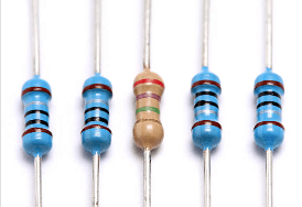
Resistor is the ability of a conductor to resist the flow of electric current. Essentially, when charges move in a certain direction within the conductor, they collide with the atomic lattice, irreversibly converting some of the electrical energy into heat (the Joule-Lenz effect).
The value of a resistor is determined by several factors:
- Material conductivity: Metals like copper have high conductivity and low resistance; insulators like rubber have very low conductivity and high resistance.
- Conductor length: Longer conductors increase the probability of collisions, and therefore the resistance.
- Cross-sectional area: Larger cross-sectional area increases the path for charge flow, affecting the resistance.
For example, a thin copper wire has significantly greater resistance than a thicker, shorter one due to the longer and more congested path for electrons.
A filament, on the other hand, efficiently converts electrical energy into light and heat through its high resistance—a prime example of a resistor’s application
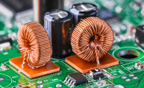
Inductor is the inherent property of a component (most commonly a coil) to resist changes in current. Its physical nature is closely related to the phenomenon of electromagnetic induction. When the current in a coil changes, a changing magnetic field is generated around it. According to Faraday’s law of electromagnetic induction, this changing magnetic field generates an induced electromotive force (self-induced electromotive force) in the coil itself, which always opposes the change in the original current (Lenz’s law).
This “resistance to change” property is similar to inertia in mechanics and is therefore called “electrical inertia.”
The inductor of a coil depends on several factors:
- Number of turns: More turns create stronger magnetic field coupling and greater inductance.
- Cross-sectional area of the coil: Larger area enhances magnetic flux and increases inductance.
- Presence of a magnetic core: The addition of ferromagnetic material can significantly strengthen the magnetic field and increase the inductance.
For example, a transformer uses the high inductance of the coil to achieve magnetic coupling for energy transmission, while a choke uses the inductor’s ability to resist AC current to stabilize DC output.
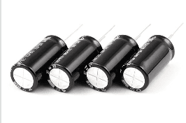
Capacitor describes the ability of two conductive plates (usually metal sheets) separated by an insulating medium (such as air, ceramic, or electrolyte) to store charge. When voltage is applied across the plates, positive and negative charges accumulate on each plate, forming an electric field and storing energy. The amount of stored charge is proportional to the voltage (Q = CU, where Q is charge, U is voltage, and C is capacitance).
The capacitance of a capacitor is determined by several factors:
- Plate area: A larger area holds more charge and therefore a higher capacitance.
- Spacing between plates: A smaller spacing increases the electric field and therefore a higher capacitance.
- Dielectric constant of the medium: A larger dielectric constant increases the charge storage capacity and therefore a higher capacitance.
The core function of a capacitor is rapid charging and discharging. In a DC circuit, it blocks DC current (in steady state, the plates are saturated, and no current flows continuously). In an AC circuit, it allows current to “pass” through cyclic charging and discharging. Capacitors are commonly used for filtering, energy storage, and DC/AC isolation. For example, filter capacitors in power supply circuits smooth voltage fluctuations and ensure stable device operation.
2. What Are the Measurement Units of Resistors, Inductors, and Capacitors in Electronic Circuits?
Resistor, inductor, and capacitor are three basic parameters in circuits, each with its own dedicated measurement units and practical application background.
Resistor
The unit of resistor is the ohm (symbol: Ω), named after the physicist Georg Ohm. One ohm is defined as the resistor that allows one ampere of current to flow when one volt is applied across it.
In practical engineering applications, resistor values vary greatly, resulting in a multi-level system of units:
Milliohm (mΩ): Commonly used to measure very small resistors, such as wire resistor and switch contact resistor. For example, a standard PCB wire typically has a resistor of several milliohms.
Kiloohm (kΩ): Commonly used in bias resistors and pull-up/pull-down resistors, such as the 4.7kΩ or 10kΩ resistors commonly used in digital circuits.
Megaohm (MΩ): Used for high-resistor applications, such as insulation resistor measurement or sensor interface circuits.
Inductor
The unit of inductor is the henry (symbol: H), named in honor of the scientist Joseph Henry. One henry is defined as the inductor that produces a self-induced electromotive force of one volt when a current changes at a rate of one ampere per second. In practical applications:
Millihenry (mH) inductors are commonly used in power supply filtering circuits, such as power inductors in DC-DC converters.
Microhenry (μH) inductors are often used in high-frequency circuits, such as RF matching networks and EMI filter design.
Power inductors in modern switching power supplies typically range from 10μH to 100μH, while inductors in high-frequency circuits can be as small as a few nanohenries (nH).
Capacitor
The unit of capacitor is the farad (symbol: F), named after Michael Faraday. One farad represents the capacity to store one coulomb of charge when one volt is applied across the capacitor.
In practical applications:
Microfarad (μF) capacitors are commonly used for power supply decoupling and energy storage.
Nanofarad (nF) capacitors are often used for signal coupling and RC timing circuits.
Picofarad (pF) capacitors are suitable for high-frequency resonant and RF circuits.
For example, a typical microcontroller power supply decoupling capacitor is 100nF, while the load capacitor of a high-frequency circuit is typically several picofarads to tens of picofarads.
3. What are the core functions of resistors, inductors, and capacitors?
Resistors, inductors, and capacitors are the three fundamental components of circuits. Each has unique electrical properties, making them crucial in shaping circuit behavior and achieving specific functions. Their specific functions can be honed based on circuit control requirements and actual application scenarios:
Resistors: Their core function is to precisely limit current and effectively divide voltage. Through their inherent resistor, resistors keep current in a circuit within a safe range, preventing excessive current from damaging sensitive components such as chips and sensors.
For example, in LED circuits, series resistors can limit the current flowing through the LED, preventing damage from overcurrent. Furthermore, using resistors of different values in series or for voltage division can provide appropriate operating voltages for different components in the circuit (for example, providing a required input voltage for a microcontroller pin). Furthermore, in analog circuits (such as operational amplifiers and audio amplifiers), resistors work together with other components to define operating conditions such as the circuit’s gain and bandwidth, ensuring accurate amplification and transmission of analog signals.
Inductors: Due to their core property of “impeding current changes,” inductors exhibit significant frequency selectivity—allowing slowly varying DC or low-frequency AC currents to pass smoothly, while significantly impeding high-frequency AC signals (i.e., “passing low frequencies and blocking high frequencies”).
This characteristic makes them widely used in filter circuits. For example, in power supply circuits, inductors and capacitors form LC filters, filtering out high-frequency ripple and outputting a smooth DC voltage. In transformers, multiple inductor coils achieve voltage regulation and energy transmission through electromagnetic coupling, making them crucial components in power systems and electronic equipment power modules. Furthermore, inductors can store energy in the form of magnetic fields. In energy storage systems (such as switching power supplies and uninterruptible power supplies (UPSs)), they can temporarily store and release energy through the charging and discharging process, ensuring continuous power supply to the circuit.
Capacitors: With their core capabilities of “rapid charging and discharging” and “charge storage,” capacitors respond extremely quickly to voltage changes, storing and releasing energy instantaneously. In power supply circuits, capacitors connected in parallel across the power supply act as “energy buffers.” When voltage fluctuates within the circuit, the capacitor rapidly replenishes or absorbs energy through charging and discharging, stabilizing the output voltage (e.g., filter capacitors at motherboard power connectors). Due to their “DC-blocking and AC-passing” properties, capacitors block DC signals within the circuit, allowing only AC signals to pass.
For example, in audio circuits, coupling capacitors transmit AC audio signals from the preceding circuit to the following circuit while blocking any DC components from interfering with the operating point of the following circuit. Furthermore, in timing circuits (such as the 555 timer circuit), capacitors, in conjunction with resistors, utilize the charge and discharge time constants to control the circuit’s oscillation period or delay time, enabling precise timing management. These capacitors are widely used in devices such as pulse generators and timers.
How do electronic components behave differently under direct current and alternating current?
The electrical response of electronic components can vary significantly depending on the type of current flow (DC, which flows steadily in one direction, versus AC, which periodically changes direction back and forth). This difference stems from the interaction between the core characteristics of the component and the behavior of the current, as shown below:
Behavior under direct current (DC) conditions
Direct current has constant magnitude and direction, and component behavior primarily exhibits steady-state characteristics:
Resistors: They exhibit a continuous and constant resistor, obeying Ohm’s law (V=IR), and continuously convert electrical energy into heat. For example, resistors are used in DC circuits for current limiting, voltage division, or as heating elements.
Inductors: At the moment of power application, their self-inductor hinders current changes, resulting in the phenomenon of “blocking AC and passing DC.” Once the current stabilizes and the magnetic field is established, the inductor acts like a short circuit (under ideal conditions), with extremely low DC resistor. For example, inductors are often used to smooth current ripples in DC power supplies.
Capacitors: During the instant of charging, they allow current to flow, resulting in the phenomenon of “passing AC and blocking DC.” Once charging is complete, the voltage across the capacitor equals the power supply voltage, and current flow ceases, effectively creating an open circuit. This characteristic makes capacitors commonly used in DC circuits for energy storage, time delays, and DC isolation.
Behavior in an alternating current (AC) environment
The magnitude and direction of alternating current vary periodically, and component behavior is strongly dependent on frequency:
Resistors: Their resistor to AC current is the same as that to DC current. Their resistor value does not change with frequency, and they still obey Ohm’s law, dissipating active power.
Inductors: In addition to DC resistor, they also exhibit inductive reactance (X_L = 2πfL). Their resistor increases with frequency, causing the current to lag the voltage by 90 degrees. For example, inductors are used in AC filtering, transformers, and motors to suppress high-frequency noise and transfer energy.
Capacitors: Their resistor exhibits capacitive reactance (X_C = 1/(2πfC)). Their resistor decreases with frequency, causing the current to lead the voltage by 90 degrees. Capacitors are commonly used in AC circuits for coupling, filtering, and phase compensation, for example, by blocking DC from AC signals.
Understanding the different behaviors of components in AC and DC conditions is fundamental to analyzing circuit frequency responses, designing filters, and optimizing power management and signal processing systems. The differences in the behavior of resistors, inductors, and capacitors in AC and DC conditions directly determine their applicability and functionality in different electronic circuits.
What factors affect the characteristics of resistor, inductor and capacitor?
The electrical behavior of resistors, inductors, and capacitors is not fixed. Their characteristics are affected by their physical structure, material properties, and external operating conditions (such as temperature and frequency). The specific factors and mechanisms of influence are as follows:
Physical Factors Affecting resistor:
Length: The longer the conductor, the greater its resistor to current flow.
Cross-sectional Area: The larger the cross-sectional area (i.e., the thicker the conductor), the lower its resistor.
Material: Materials such as copper and silver have good conductivity and low resistor; rubber and plastic have poor conductivity and high resistor.
Temperature: As temperature rises, the resistor of metals increases, while the resistor of semiconductors generally decreases.
Frequency: As the frequency of alternating current increases, the current becomes more concentrated on the surface of the conductor (skin effect), increasing resistor.
Impurities: Added impurities can increase or decrease resistor depending on their effect on conductivity.
Factors Affecting Coil inductor:
Number of Turns: The more turns a coil has, the greater its inductor.
Coil Length: The longer the coil, the lower its inductor.
Cross-sectional Area: The wider the cross-sectional area (i.e., the thicker the coil), the higher its inductor. Core Material: Magnetic materials such as iron and ferrite can increase inductor.
Coil Shape: Different shapes can affect the formation and performance of the magnetic field.
Frequency: At higher frequencies, core losses and parasitic effects can alter the inductor’s behavior.
Temperature: Heat can alter the core’s magnetic properties, thereby changing the inductor.
Factors Affecting Coil capacitor
Dielectric Material: A higher dielectric constant increases capacitor.
Plate Area: A larger plate area can store more charge.
Plate Spacing: A smaller gap between the plates increases capacitor.
Dielectric Strength: Materials with higher dielectric strength can safely withstand higher voltages.
Temperature: Heat can affect the insulating material’s ability to store charge.
Number of Plates: A greater number of plates connected in parallel increases the total capacitor.
By systematically analyzing the physical nature, measurement units, functions, behavioral differences in AC and DC environments, and factors influencing their characteristics, we gain a comprehensive understanding of the working logic and application patterns of these three basic circuit components. They each have unique electrical properties that are both distinct from each other and work synergistically in the circuit to achieve the regulation of electrical energy and the fulfillment of circuit functions.
Whether it is circuit design, equipment maintenance, or the study and research of electronic technology, a deep understanding of this knowledge is an indispensable foundation. Mastering this content will not only help us more accurately analyze circuit behavior and optimize circuit performance, but also lay a solid foundation for subsequent exploration of more complex electronic technology fields, promoting more efficient and reliable innovation and application in electronic engineering-related practices.
Product Center Guide:
Want to learn more about high-quality resistors, inductors, and capacitors? Visit our Product Center for complete specifications and pricing to help you design and manufacture your electronics.
Industry News/Learning:
Want to gain a deeper understanding of resistor, inductor, and capacitor applications and the latest technology trends? Browse our Technical Blog for practical information and case studies.