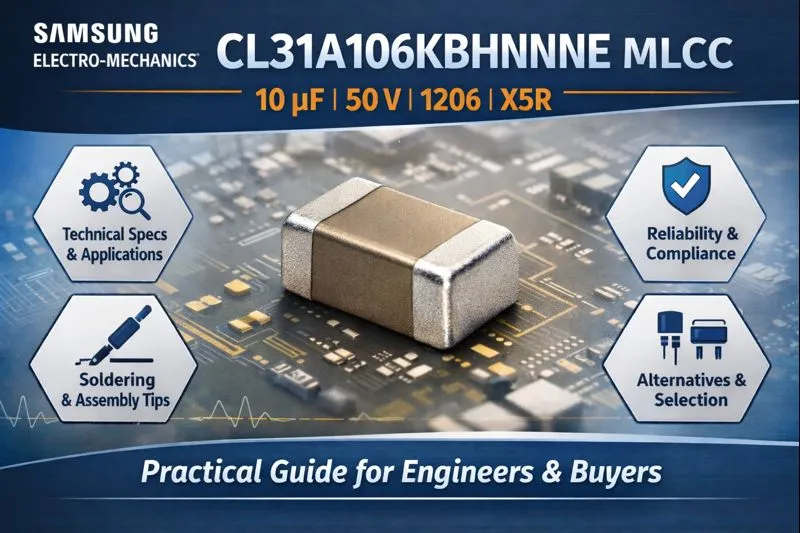
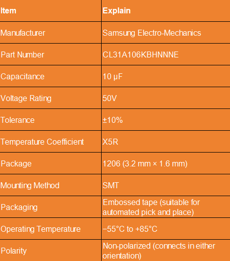
As an MLCC solution, the Samsung Electro-Mechanics model CL31A106KBHNNNE is a general-purpose 10 µF, 50 V X5R multilayer ceramic capacitor (MLCC) in a 1206 (3.2 × 1.6 mm) package using surface mount technology (SMT). This capacitor is compact and easy to mount and reflow. It is commonly used for energy storage, decoupling, and bypassing, effectively suppressing noise and ripple in circuits. It is widely used in consumer electronics, computer equipment, and power module designs. This article will analyze the CL31A106KBHNNNE’s key technical references, common applications, design considerations, manufacturing and soldering recommendations, storage and reliability requirements, and possible alternatives and selection options.
This article provides practical technicals references for circuit designers and procurement engineers, helping them integrate these MLCC components more efficiently and safely in real-world projects.
Key Technical Specifications of Samsung CL31A106KBHNNNE MLCC
According to the electronics supplier’s product listing, the CL31A106KBHNNNE has the following features:
Note: The above table is a summary of core specifications. For complete measurement conditions (such as capacitance measurement frequency and bias conditions), environmental, and reliability test details, please refer to the official Samsung Electro-Mechanics datasheet.
What are some common applications of CL31A106KBHNNNE MLCC?
The CL31A106KBHNNNE, due to its capacitance/voltage ratio and compact package, is suitable for a variety of PCB design applications, such as:
- Computers: Motherboard decoupling, solid-state drive (SSD) power supply filtering
- Mobile devices: Power supply regulation/bypassing for smartphones and tablets
- Display devices: Power supply filtering and local decoupling for TVs and monitors
- Game consoles and consumer electronics: Main power supply and subsystem decoupling
- Power electronics: Input/output bypassing for DC-DC converters (depending on ripple and current requirements)
Design engineers should evaluate whether to use a single MLCC or combine it with other capacitors (such as tantalum or solid-state capacitors) for optimal performance based on the ripple current and equivalent series resistance (ESR)/equivalent series inductance (ESL) requirements of their specific circuit.
Design Considerations for MLCC Integration
- Voltage and temperature limits: Ensure that the actual operating voltage is ≤ 50 V and the operating temperature is within the −55°C to +85°C range in your circuit design. High temperatures and high-stress environments can cause capacitance characteristics to drift.
- DC Bias Effect: X5R material exhibits capacitance drop when DC bias is applied (the 10 µF rating is measured under specific conditions, such as 1 Vrms, 1 kHz). The actual usable capacitance is often lower than the nominal value near the rated voltage. When higher effective capacitance is required, please consult the supplier’s DC-bias curve and allow for margin.
- Temperature Coefficient and Frequency Response: X5R capacitance will vary somewhat with temperature and frequency. If the circuit requires precise capacitance or low drift, consider using a more stable dielectric or adding compensation circuitry.
- Mechanical Stress and PCB Layout: Avoid placing MLCCs in areas of the PCB that are prone to flex or mechanical stress (such as board edges, near connectors, and areas subject to high reflow stress). Provide adequate pad support during routing and avoid introducing stress concentration points in the circuit to reduce the risk of cracks.
- Parallel and bypass solutions: When reducing ESR/ESL or extending the frequency band, capacitors of different capacitance values are often used in parallel with the package (for example, a 10 µF MLCC + a 0.1 µF high-frequency bypass capacitor) to obtain a flatter impedance curve.
Manufacturing, Assembly, and Soldering Recommendations for MLCC
- Reflow Oven: Recommended peak reflow temperature: 260 ± 5°C, with a maximum allowable peak time of 30 seconds (refer to the manufacturer’s data sheet).
- Re-soldering (Hand Soldering Iron): For repair soldering, use a soldering iron for short, spot soldering; the data sheet often lists the allowable hand soldering temperature (e.g., 245 ± 5°C, 3 ± 0.3 seconds)—refer to official regulations.
- Solder Paste: Lead-free solder paste (e.g., Sn-Ag-Cu series) is recommended. Follow the PCB thickness and solder paste printing process to minimize bridging and cold solder joints.
- Test Board Recommendations: For performance testing, use FR-4 (glass epoxy) boards with a copper foil thickness of approximately 0.035 mm to ensure comparability.
- Packaging: Products are typically supplied on embossed tape and reel, suitable for automated placement (please confirm tape width, mandrel hole position, and spacing parameters according to the pick-and-place machine specifications).
Handling and Storage Precautions for MLCC
- Electrostatic Discharge (ESD): Observe ESD precautions during handling and assembly (grounding, wearing an anti-static wrist strap/clothing) to prevent potential damage.
- Storage Environment: It is recommended to store the device in a controlled environment (temperature and humidity controlled, free from moisture and contamination). Some products are moisture-sensitive. Once opened, follow the dehumidification/drying instructions (refer to the datasheet or the supplier’s packaging instructions).
- Shelf Life and Dehumidification: If opened after extended use or in a high-humidity environment, follow the manufacturer’s baking and re-drying recommendations to prevent solder joints or solder defects.
Design Alternatives and MLCC Selection Recommendations
If more stable capacitance values (low DC bias and temperature drift) are required: Consider ceramic materials with lower temperature drift or mix and parallel other capacitor types (such as solid tantalum or aluminum electrolytic/polymer) to meet ripple current and stability requirements.
If the operating voltage or ripple current exceeds the limits: Select MLCCs with higher rated voltages or larger packages/higher rated current capabilities, or parallel multiple capacitors to share ripple current and heat rise.
When replacing/upgrading, pay attention to DC-bias curves, ESR, ripple current capability, and consider 7SEtronic compatible MLCC alternatives to meet specific design requirements.
Reliability and Compliance Standards for MLCC
This type of MLCC is generally evaluated for reliability through standard thermal cycling, humidity, and mechanical shock and vibration tests. Compliance with RoHS, AEC-Q, or specific automotive-grade requirements should be determined based on Samsung Electro-Mechanics’ official datasheets and certification statements. For high-reliability applications such as automotive, medical, or aviation, please confirm that the component grade and certifications meet the corresponding industry standards.
For the most accurate electrical parameters, performance curves (such as DC bias and temperature characteristics), package dimensions, soldering specifications, and reliability data, please refer to Samsung Electro-Mechanics’ official datasheet. Complete technical documentation for this model, CL31A106KBHNNNE, is available for download on the Samsung Electro-Mechanics website and through authorized distributors such as Future Electronics, DigiKey, and Mouser.
Overall, the CL31A106KBHNNNE is suitable for a wide range of consumer and industrial electronics, offering a good capacitance-to-volume ratio and manufacturing compatibility. However, in actual designs, consideration must be given to the impact of DC bias, operating temperature, PCB mechanical stress, and soldering process on the effective capacitance value and reliability.
Before making a final selection, it’s recommended to consult Samsung Electro-Mechanics’ official datasheet (including DC-bias curves, temperature characteristics, and soldering specifications). Based on ripple current and ESR/ESL requirements, designers may consider paralleling small-capacitance capacitors or adopting a mixed capacitor solution. For BOM optimization suggestions or engineering support for compatible alternatives, 7SE offers long-term supply and application support to help engineers integrate appropriate MLCC components more smoothly during the design phase.
FAQ 1: Does CL31A106KBHNNNE really deliver 10 µF in actual operation?
Not always. As an X5R MLCC, its effective capacitance drops under DC bias, especially at higher voltages. The nominal 10 µF is measured under specific test conditions. In real designs, engineers should check the DC-bias curve and allow margin, or parallel multiple capacitors if stable effective capacitance is required.
FAQ 2: Can this MLCC be used in DC-DC converter input or output circuits?
Yes, under moderate ripple and current conditions. For higher ripple current or stricter ESR/ESL requirements, it is recommended to parallel multiple MLCCs or combine it with polymer, tantalum, or electrolytic capacitors for improved stability and reliability.
FAQ 3: What are the key PCB layout and soldering risks to watch out for?
Mechanical stress is the main concern. Avoid placing the capacitor near board edges, connectors, or high-stress areas. Follow the recommended reflow profile and proper pad design to reduce the risk of MLCC cracking and ensure long-term reliability.
For more information and to review our available inventory, please contact our team for detailed pricing, current stock levels, and any additional technical support you may need.
You can find more component guides and application notes in our Component Technical Guides section: